John Kobbe remembers his early days at Tektronix.
I had just gotten out of the Navy in late 1951 and was planning to use the G.I. bill for college but in the meantime I needed a job. After interviewing a few possibilities like Portland radio shops and an interview with a recruiter from United Airlines who told me that they would let me know. I went to the Chamber of Commerce to find what else electronic might be going on and found out there was this company over the hill and out in the country that manufactured oscilloscopes. I walked into Tektronix and they showed me around. I was impressed with them and I guess they were impressed enough with me that they asked “When could you come to work to test and calibrate scopes?” I said I was ready now, so they asked if 7 AM the next morning would be ok.
The product line was mainly the updated Model 511, 514 ( d.c. coupled vertical otherwise similar to the 511), 512 (a low frequency high gain d.c. vertical amplifier with a very slow sweep speed), and the state of the art 513 with a bright cathode ray tube ( CRT) with about 25 megacycles, (not mega Hz in those days). There was a special purpose 517 for nuclear explosion tests.
With Tek’s blessings, a group of five or six of us formed a scope class to design and build an oscilloscope. We would not copy anything and keep it as simple as we could. A month or so on, we had the vertical system, horizontal amplifier, and CRT circuits (except the unblanking). The vertical was to have a 10-1 variable gain, 10 times and 100 times attenuator, no signal delay line with about 3 or 4 MHz band width.
We were having problems figuring out a simple time base (sweep) circuit. On a coffee break I cornered Dick Ropiquet, who had just finished a wide range sweep for the 315 scope, he described all the functions of an idealized sweep circuit. The 315 sweep was more complicated than what we wanted to use, so I set out to find a simple way to keep all the needed requirements but kept coming to dead ends. Finally a circuit made all the way around the loop and was simple enough for our scope.
The scope class was fairly well known within the company. Sandy Sanford and his secretary had their desk just through a door on the other side of the wall from my bench. One of Sandy’s job was to take care of field technical problems. When he didn’t have an answer, it was easy for him to step through the door and discuss the problems with us. One of the common problems was the intensity (brightness) needed adjusting after a duty cycle change. Not too bad if it got brighter but when it disappeared the customer would sometimes get totally lost. The unblanking not only needed to be solved for our scope class but for Tek’s new designs. I decided to start a list of all different ways I could think of and adding to the list for the next week or so, then picked the one that looked most promising which was the floating power supply. The first thought was that it was too complicated, but when you look at how it is done, it isn’t really that bad.
I came in early one morning and put together needed circuitry, hanging it out the side (so it would be easy to put back to normal) of an upside down scope which I was supposed to be calibrating. Went into engineering, explained the idea and like my first thoughts, they were doubtful. When they found out that there was one hay-wired together on my bench, Frank Hood said he would come look at it, as he needed a better unblanking system for a new portable scope ( would be called the 310). He liked what he saw and thought that some more engineers should come look at it. Frank also wanted our sweep for his new scope.
I soon found myself in engineering and the scope class came to an end, but I guess you could say it sort of lives on as a 310. My first job was modifying the production scopes to use the unblanking circuit. After that was done, I started learning and helping with the new generation scopes that were to become the 530 series.
Everyone in the whole company was trying to come up with the best we could do. I also learned a lot about engineering.
Tek had committed to develop and manufacture a CRT for the new scopes (one of the best moves that Tek ever made) but they were falling behind and not coming up with the right compromise. Since I had become fairly familiar with what could be done circuit wise; I was asked to move to the CRT department to help make the CRT compromises. The design goal was to have 6 cm of vertical display with a sensitive good enough to make band width of 10 mhz. It turned out that the sensitivity was about as good as we could do with out major changes in the CRT design.
Bill Polits decided as last resort to use cathode followers to drive the deflection plates. That worked fine except for large signals which would be limited by the slew rate. It was practically no problem for on screen signals but became significant when driven off screen.
The main problems were geometry problems. I realized that if they had a cross hatch generator, in one quick look they could see all of the problems. So I threw one together. The geometry problems turned out to be magnetized gun parts and also charges building up on glass surfaces. We ended up with a producible CRT just in time so as, not to hold up shipments of the new 530 series (531 and 535) scopes. In the meantime I was visualizing a vertical amplifier system that could be about 2 or 3 times faster if the deflection was limited to 4 cm vertical display, instead of 6 cm. I had free access to use most any equipment, so during the weekend I went in and using tin snips, pliers, files and whatever else was there, to have the (4 cm vertical deflection) CRT ready to pump down Monday morning, the glass work was not very pretty but worked ok. The CRT performed as expected and I was soon working on the amplifier, utilizing that CRT which became the 540 series. We had talked about a balanced signal delay line for the 530 series but it was thought it would take too long to develop. The plan for the 540s was to put a distributed amplifier physically near the plug in and continue its output into a balanced delay line ending at the CRT deflection plates. Dick Rhiger did the mechanical layout, coil mounts etc. We adjusted the center taped coils for optimum transient response (Previous Tek delay lines used 1.55 to 1 length to diameter ratio that a PhD had calculated but he probably did not count on the stray capacitance). We first used a ratio of one to one. We lucked out that it was about right. The delay line needed some common mode damping. Another anticipated problem with passive probe,we knew a signal bounced back and forth so we could not use the standard probe. While thinking about things to do like some damping resisters. Why not us a fine resistance wire as the center conductor. This time we really lucked out, it worked better than anticipated. It was even patent-able as was unblanking and sweep circuit.
Later on there was another special CRT designed with a distributed vertical deflection for the 100 Megahertz 580 (well almost 100 MHz). The 580 was the first to, at least at Tek, to use a cross wound continuous signal delay line. The 580 used a similar horizontal system lifted from the 530’s which was too slow and insufficient writing rate. The active probe and plug in system left a lot to be desired. I wasn’t very proud of the 580 design as it was too compromised.
While I was working on the 540 series vertical amplifier, Virgil Briton, whose bench was next to me, had put together a vacuum tube curve tracer using stepping relays and other mechanical devices. I remember thinking that, that was a neat display even if it did a lot clicking and was slow. After putting the cross hatch generator together, I knew it would be very easy to do the curve tracer electronically,it started for in house use,but after putting a self-contained instrument together, Tek decided to call it 575 and sell it.
When transistors started to become practical, Tek sent Bill Polits to Michigan, for a 2 week primer on transistors. He in turn communicated it to the rest of us who were interested. That called for a transistor curve tracer. It used a similar step generator as the tube curve tracer but other wise needed mostly new circuits. I remember a day at the beach, I was trying to hide from the sun while everyone else was getting their sunburn. I dug the sand out from under our new 1954 Chevy, got comfortable and figured out the circuits for the curve tracer soon to become the 575. Dean Kidd did the hard part when he designed the switches.
It seems the 50’s and into the 60’s was the real heyday for Tektronix during which period there were really no high powered engineers. We learned from each other and pretty much used everyone’s ideas in the designs. This applied not only to Engineering, but to all departments.
Starting in the 60’s (maybe coinciding with the move from the Sunset building) engineering and research became compartmentalized. To me it seemed that the allegiance went to their department instead of the company.
Never in my wildest dreams did I expect to end up with such and interesting and fun job while contributing to the industry in a small way. Ever since I can remember I was, playing, building, and experimenting with electrical stuff. Previous to Tek I used to build electronic stuff and somehow make things work. In my early experience at Tek, I learned from others how to predict, build and have it work (well, most of the time).
If I remember correctly, these are the people that were working in engineering in 1951: Logan Belleville, Henry Hayes, Frank Hood, Dean Kidd, John Larsen, Cliff Moulton, Chuck Nolan, Bill Polits, Dick Rieger, Dick Ropiquet, Rodgers Jenkins, Howard Vollum (who was mostly busy with management).
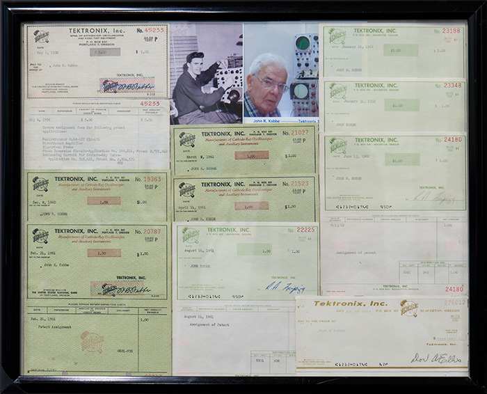
John donated his patent checks to the museum and we have them on display. In the early years patent recipients were presented a check for $1.00 for their patents. Later they were recognized at the Inventors Recognition Banquet.